Image:Mutually inducting inductors.PNG
From Wikipedia, the free encyclopedia
No higher resolution available.
Mutually_inducting_inductors.PNG (231 × 174 pixel, file size: 3 KB, MIME type: image/png)
Summary
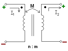
A picture of the usual depiction of mutual inductance. The two verticle lines between the inductors indicate a solid core that the wires of the inductor are wrapped around. "n:m" shows the ratio between the number of windings of the left inductor to windings of the right inductor. This picture also shows the dot convention.
Licensing

I, the creator of this work, hereby grant the permission to copy, distribute and/or modify this document under the terms of the GNU Free Documentation License, Version 1.2 or any later version published by the Free Software Foundation; with no Invariant Sections, no Front-Cover Texts, and no Back-Cover Texts.
Subject to disclaimers.
File history
Legend: (cur) = this is the current file, (del) = delete this old version, (rev) = revert to this old version.
Click on date to download the file or see the image uploaded on that date.
- (del) (cur) 01:32, 19 October 2006 . . Fresheneesz ( Talk | contribs) . . 231×174 (2,774 bytes) (Fixing picture along with another. This has been wrong for months)
- (del) (rev) 01:48, 15 April 2006 . . Fresheneesz ( Talk | contribs) . . 231×174 (2,789 bytes) (A picture of the usual depiction of mutual inductance. The two verticle lines between the inductors indicate a ''solid core'' that the wires of the inductor are wrapped around. "n:m" shows the ratio between the number of windings of the left inductor to w)
-
Edit this file using an external application
See the setup instructions for more information.
File links
Category: User-created GFDL images